Advanced настройки Wi Fi роутера. Вопрос к беспроводным спецам
К нему подключаются 4 устройства тоже с n адаптерами (одновременно работает не более двух). Скорость меня не очень устраивает, поэтому я решил подшаманить что-нибудь в в настройках беспроводной сети.
Установлена прошивка Tomato. В ней на закладке Advanced — Wireless есть некие параметры. Какими их лучше задать? Кто что знает помогите. Для удобства сделал скриншоты с возможными значениями параметра.
— 
Afterburner – одна из технологий увеличения скорости при использования протокола 802.11g. «Ускорение» достигается за счёт удаления из передаваемых данных «лишней» служебной информации, при этом остаются лишь те данные, без которых нельзя обойтись. Кроме того, используется сжатие данных и принудительное ускорение передачи пакетов. Такое оборудование можно отличить, например, по логотипам SpeedBooster или «125 High Speed Mode».
Стоит включать или нет?
********************************* 
Ничего не нагуглил по этому поводу. Но скорость в 1-2 мегабита смущает =)

Ничего не нагуглил.

CTS Protection Mode (Режим избирательной передачи). Эта функция усиливает способность точки доступа принимать все передачи стандарта 802.11g, но сильно уменьшает производительность сети. Выберите Enable, если вы хотите временно разрешить эту опцию или оставьте настройку по умолчанию — Disable, если вы хотите ее отключить. В большинстве случаев CTS Protection Mode следует оставлять отключенным и включать ее только в ситуации сильных затруднений при передаче сигнала точке доступа в зоне действия чрезмерного трафика стандарта 802.11b.

Frame Bursting дает возможность увеличивать пропускную способность соединения при обмене данными между 802.11a, b или g устройствами за счет снижения расходов, возникающих при работе в беспроводных сетях.
Включать или нет??

Что за фрукт такой? И где мои бешеные 150 мегабит n стандарта? =)

Что за преамбула такая?


Опять же, где мои бешенные 150 мегабит? =)
Всем заранее спасибо за помощь
- Вопрос задан более трёх лет назад
- 25991 просмотр
- Вконтакте
- Вконтакте
- Вконтакте
- Вконтакте
- Вконтакте
- Вконтакте

Думаю все-таки поддерживает. Вот скрин с приконнекченого ноута.
Но вот реальная скорость конечно далека от той, что на картинке
- Вконтакте

Точка выдется как n, все ништяк
- Вконтакте
- Вконтакте
The preamble is used to communicate to the receiver that data is on its way. Technically speaking, it is the first portion of the Physical Layer Convergence Protocol/Procedure (PLCP) Protocol Data Unit (PDU). The preamble allows the receiver to acquire the wireless signal and synchronize itself with the transmitter. A header is the remaining portion and contains additional information identifying the modulation scheme, transmission rate and length of time to transmit an entire data frame.
* Compatible with legacy IEEE* 802.11 systems operating at 1 and 2 Mbps (Megabits per second)
* PLCP with long preamble is transmitted at 1 Mbps regardless of transmit rate of data frames
* Total Long Preamble transfer time is a constant at 192 usec (microseconds)
* Not compatible with legacy IEEE 802.11 systems operating at 1 and 2 Mbps
* PLCP with short preamble: Preamble is transmitted at 1 Mbps and header at 2 Mbps
* Total Short Preamble transfer time is a constant at 96 usec (microseconds)
What does this all mean to the end user?
Most access points (AP) and broadband Wi-Fi routers are configured for a Long Preamble or have a setting that automatically detects the preamble and adjusts accordingly. A majority of client Wi-Fi adapters should also be pre-configured in the same manner. This is done as a precautionary measure for networks that may still employ legacy devices. It is not recommended you make changes to default settings. If this becomes necessary, consult with your equipment manufacturer before taking such action.
Advanced Wireless
The Advanced Wireless menu contains settings for advanced tuning of WiFi interfaces. Changing these settings from the defaults is not recommended unless you are experienced with advanced WiFi settings. All default settings in the dropdown menus on this page are noted with an asterisk (*). For basic WiFi settings, see the wiki page for the Network menu.
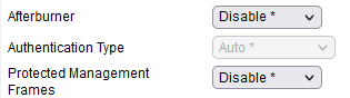
Afterburner
(Note: only valid for MIPS RT & RT-N branch/images, NOT ARM (no support))
Enabling Afterburner turns on support for Broadcom's frame-bursting and compression technology to improve 802.11g wireless throughput. This feature is also known as 125 High Speed Mode (or 125HSM) and goes by other names with other hardware vendors. Theoretically, this boosts signalling rates to 125 MB /s. Realistically, one can expect 30-40 Mb/s throughput in real world environments. Since this is a proprietary protocol extension, effectiveness will vary depending on the client device maker as well.
Authentication Type
This option controls whether clients must use shared keys to authenticate. Shared Key is disabled in some wireless security modes, for compatibility.
Protected Management Frames
Three configuration options exist for Protected Management Frames (PMF). [Note: Protected Management Frame (PMF) feature is also known as Management Frame Protection (MFP)]
By default, this wireless security enhancement option is disabled because not all wireless clients support it. Support for this option is available starting with release 2021.6 (only for ARM hardware).
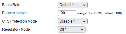
Basic Rate
The Basic Rate Set is a list of rates at which the router reports it can sync. with wireless client devices. A router regularly broadcasts the Basic Rate Set in its beacon packets. In this way, wireless clients in your network know which rates will be used. The Router will also advertise that it will automatically select the best rate for transmission.
Default: Tomato advertises that it can sync. at all standard wireless rates. This includes: 6, 9, 12, 18, 24, 36, 48, and 54 Mbps in addition to the 802.11b rates of 1, 2, 5.5 and 11Mbps.
1-2 Mbps: This setting is sometimes required for compatibility with 802.11b clients, if they don't connect via the Default setting.
All: This setting makes Tomato advertise all wireless rates supported in hardware.
Beacon Interval
This specifies the period of time between one beacon broadcast and the next. A beacon is a packet broadcast by the router to synchronize the wireless network and serve other administrative functions. (Default: 100 ms).
CTS Protection Mode
This function could more appropriately be called RTS/CTS Protection Mode. Wireless client devices transmitting to a router cannot detect when other devices on the same network are also transmitting. When more than one client transmits at a time, data collisions occur. The router is then forced to discard data from both clients. This increases error rates and reduces speed. When Clear-to-Send Protection is on, a computer must send a RTS (Request to Send) frame to the router. This is basically a request to be allowed to transmit at that moment in time. In return, the router must send back a Clear-To-Send frame indicating the client can send data. In this way, CTS Protection Mode determines the order in which computers contact the access point/router. Typically, CTS frames are not sent/needed until the client has a data frame to send that meets a certain size threshold. That threshold frame size can be set in the RTS Threshold field. See below for details about that setting. CTS is typically used for 802.11b/g/n/ac protocols. RTS-CTS is typically used with 802.11a/b/g protocols.
Auto: determines which computer can reach the FreshTomato router at a specific time through CTS and its send (RTS) packet. Disabled is the recommended setting, since well-designed networks rarely need it. However, if you are experiencing lots of physical layer collisions, then you might try enabling this and tuning the RTS Threshold setting.
Regulatory Mode
This option lets you choose which wireless standards are followed. Countries (usually adjoining) that share a common set of regulations are referred to in the 802.11 specification as regulatory domains. Four major regulatory bodies have authority over almost all of the world's technology regulations:
Each domain has strict regulations for parameters such as antenna gain, transmit power, channel selection. Many countries choose to adhere to the standards completely. A few countries modify an existing standard to their own unique needs. This can create complications.
802.11d: This supplemental standard adds the requirements and definitions necessary to allow 802.11 wireless equipment to operate in markets not served by the current standard. This includes anywhere other than the Americas (FCC), Europe (ETSI), Japan (TELEC), China, Israel, Singapore, and Taiwan. [1]
802.11h: 802.11h is the IEEE standard for Spectrum and Transmit Power Management Extensions. It solves problems like interference with satellites and radar using the same 5 GHz frequency band. The standard provides Dynamic Frequency Selection (DFS) and Transmit Power Control (TPC) to the IEEE 802.11a MAC. (Media Access Control layer).

Country / Region
(Default: Singapore / 12) [ARM]
Country code AND rev(ision) define the possible channel list, power and other regulations for each country. The current wireless driver (year 2020 and newer) supports approximately 290 countries and 2000 combinations of country code and revision.
SDK6 Example Country / Region and Country Rev choices (ARM Router):
SDK7 Example Country / Region and Country Rev choices (ARM Router):
SDK714 Example Country / Region and Country Rev choices (ARM Router):
Example Country / Region and Country Rev choices (MIPS Router, RT-N and RT-AC):
Some combinations of Country and revision codes are invalid, and will not work together. For example (ARM router), if you set country to USA, and change only country to “US” and leave revision at “12” that would be invalid. You need to change country / region to “US” and country revision to “0” to have a working combination.
Many users will be able to choose the correct settings from those in the Wireless menu. However, there are many more settings.
Advanced users can see the complete list of settings and their code commit entries here:
For SDK714 ARM router:
Not available so far!
Example: for SDK6 (ARM models only) builds and country USA, open file “wlc_clm_data.c”
(sysdeps/RT-AC68U/clm/src/wlc_clm_data.c) and go to line
98738. There, you will see the following:
The comment field on the right contains valid country and revision combinations. You can see that country “US” and country rev “12” is NOT a valid setting for the wireless driver. Do not use “#a” or “#r”. They are special values for testing and not for regular use.
For MIPS SDK5 (RT) builds, there is only a country selection setting.
Starting with MIPS SDK6 (RT-AC) builds and all ARM-Branches/Versions you will need to choose a country and a country rev. This applies to release 2020.6 and later. With release 2022.4 and later user will need to choose a country and a country rev for RT-N router also!
Further Note for Asus Router: To check what country code & country rev is stored at the bootloader (factory default value for this router), please try/use the following system commands.
Example for RT-AC66U_B1 ARM router:
For (some) older Routers: Some combinations may not be longer support by the wireless driver, see for example.
To get or check the current wl country setup:
Country Rev
See the Country/Region section above. Revision settings only exist in FreshTomato 2020.6 and later. For Mips SDK5 (RT-N) support added with release 2022.4 and up!
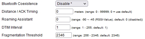
Bluetooth Coexistence
The Preemptive function will make FreshTomato inform the Bluetooth device about which Bluetooth channel it's operating on. The Bluetooth device can then mark that channel as “in use” and use alternate channels for its own communications.
The Bluetooth devices must support the Bluetooth Coexistence function, or they will be unable to share nicely and this option will have no effect.
NOTE: This option is available only on 2.4GHz.
Distance / ACK Timing
When a router sends a packet to a client, it waits for an ACKnowledgement frame from the client to ensure the packet was received. The time period the router waits for that acknowledgement is called the “ACK timeout” (or “Timing”). Traditionally, ACK Timing is set to the maximum distance of the furthest client device in meters x 2. The doubling is to account for the round-trip distance/time, including the time it takes for the client to receive the packet, and the time for the response to travel back to the router. For example, if you roam with your laptop up to 50 meters from your AP, the setting would be 100. Generally, the default is recommended, except where administrators have a strong knowledge of timing or are building long-distance wireless links.
Typically, 802.11b/g has a range of less than 100 meters. Therefore, one might assume this should never be set higher than 200. However, in scenarios with high power antennas or other long-range gear, the timing settings would need to increase. Longer distance links have been established far beyond the theoretical limits of 802.11 b/g.
However, higher ACK Timing comes at the cost of lower throughput. If set too high, packets could be lost as the router waits for the ACK window to timeout for ACK frames that were never going to arrive. It will also resend the “unacknowledged” packet to the client, thinking it might not have received it yet. If ACK Timing is too low, the router may drop returning ACK frames too early, and again resend the original “unacknowledged” packet. This too might lower throughput.
Roaming Assistant
After enabling the Roaming Assistant, you can define the value for disconnecting clients with RSSI lower than -XY dBm (Valid range: -90 to -45) from your wireless radio unit (eth1/eth2/eth3).
Support for this option is available starting with release 2022.1 (ARM & MIPS hardware; Some MIPS router may not include the option).
DTIM Interval
A Delivery Traffic Indication Message (DTIM) message is a field included in some beacon frames. It informs clients that the access point/router has buffered or multicast/broadcast data to receive. When in power-save mode, a client device may sleep for one or more beacon intervals, then wake up for beacon frames that include DTIMs. A DTIM message notifies sleeping clients that they will need to wake up to receive the waiting frames.
The DTIM Interval specifies how often a beacon frame includes a DTIM message, expressed as the number of beacon frames that will be sent before a DTIM is included in a beacon frame. DTIM Interval values range 1 to 255. The DTIM Interval value is included in each beacon frame. Following a beacon frame that includes a DTIM, the router will release any existing buffered broadcast and/or multicast data. This means that the DTIM message is included in every second beacon frame.
In other words, wireless clients may have conflicting requirements for power consumption and communication throughput when in power-save mode.
Fragmentation Threshold
IP fragmentation is the process of the IP layer breaking down datagrams into smaller pieces (fragments). The destination host, or sometimes intermediate routers reassemble the fragmented pieces to make the message whole again. This is usually done to reduce the size of the datagrams so that the pieces can pass through a link with a smaller MTU than the original datagram size.
This option specifies the maximum size of datagram that can occur before it is fragmented into multiple datagrams. Similar to RTS Threshold, tuning the Fragmentation Threshold setting may reduce frequent collisions on the network. Too low values may cause poor network performance. The default setting is recommended.
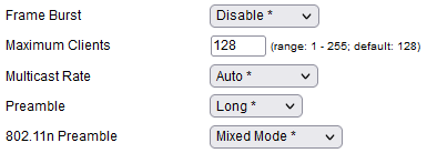
Frame Burst
Frame-bursting is a link layer protocol used to increase the throughput of connections on links between 802.11a/b/g/n hosts under certain network conditions. It does this by reducing the overhead used in the wireless session between hosts. It grew from standards first introduced in the 802.11e QoS specification for link layer connections.
Network protocols for shared media are designed so that any host that has sent a MAC layer frame is then supposed to yield the medium and wait for a fixed period of time. This helps create a fair use of the medium by multiple users.
Frame bursting allows wireless clients to upload data at faster speeds by using the wait intervals between frames to “burst” a series of up to three frames before waiting the required period. As usual, there are compromises. Frame Burst can cause unfair allocation of airtime on networks where where only some clients support Frame Burst. The wait periods between frames were not originally designed to include data traffic. The recommended setting is Disabled, unless there are very few hosts on your network. Broadcom's implementation of this feature is called “Express Technology”.
Maximum Clients
This specifies the maximum number of clients that can be connected to the wireless network. It is not recommened to increase this number, as the likely result will be an overloaded network with slow throughput. There is little harm in testing a lower number. This can be useful to reduce network traffic, or for security purposes.
Multicast Rate
This setting controls the rate at which hosts can send multicast packets to a multicast group. Traffic exceeding this rate is discarded. Optimizing this rate can lower collisions, especially when multiple devices or services are being run at the same time. Optimization may be essential for applications which stream video and corporate communications.
For small, basic networks, the default should work fine. However, on larger networks, it's recommended that you adjust this setting. Typically, switching to the lowest setting is the quickest, easiest way to optimize your system. However, networks with more client devices will likely require higher settings to be effective. Setting this too high can impact performance, so you may need to test to ensure that your setting isn’t using up all of the bandwidth on just one device.
Preamble
In wireless networking, the preamble (or “header”) is a section of data at the head of data link layer frames which contains information wireless devices need to send and receive data. Part of the preamble involves the length of the CRC (Cyclic Redundancy Check) block for communication between the router/AP and roaming wireless adapters. CRC is commonly used to detect data transmission errors.
Generally, all wireless devices on the network should use the same preamble type. If they don't, they will have trouble communicating. On some legacy wireless equipment, Preamble type may bet set with a physical switch. Current hardware has this setting available in its web interface or command-line interface.
The deafult setting is Long, to maintain compatibility with older equipment. Long preamble is also recommended for longer-distance connections or links with weak signals, since both require more extensive error checking. The Short preamble can be used on modern equipment which transmits strong signals in a fairly low-interference environment.
802.11n Preamble
For an explanation of basic concepts of the wireless preamble, see the Preamble section above.
Auto: TBD.
Mixed Mode: Mixed Mode transmissions can be decoded by 802.11a/g clients, providing backwards compatibility. In Mixed mode, 802.11n devices transmit a legacy format preamble, followed by an HT format preamble and a legacy radio signal. A Mixed mode device must also send legacy format CTS-to-Self or RTS/CTS (Request to Send/Clear to Send) frames before transmitting. These mechanisms let other 802.11a/b/g devices sense a busy network medium and wait for another turn to transmit. This allows for backwards compatiblity with earlier protocols, but reduces throughput, compared with Greenfield, or GF-BRCM modes.
Greenfield: This 802.11n mode is also known as “High Throughput” or “HT” mode. In this mode, the protocol improves efficiency by using a high throughput modulation method and a shorter preamble. Neither of these is supported on 802.11a/b/g devices. This preamble mode compromises backwards compatibility and can reduce throughput on some 802.11n devices not fully compatible with the standard.
GF-BRCM: TBD.
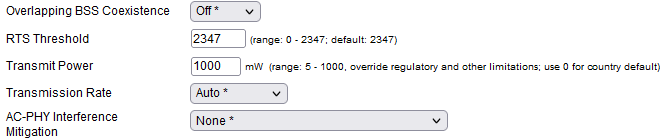
Overlapping BSS Coexistence
RTS Threshold
When CTS (Clear-to-Send) Protection is on, a host must send an RTS (Request-to-Send) frame to the router to obtain permission to transmit data frames at that time. In return, the router must send back a Clear-To-Send frame, indicating the client can send data. In this way, CTS Protection Mode determines the order in which computers contact the access point/router. Typically, CTS frames are not sent/needed until the client has a data frame to send that meets a certain size threshold. That threshold frame size is set here, in the RTS Threshold field.
Transmit Power
This allows you to override regulatory and other limitations and increase or lower the Transmit Power, in mW (milliwatts). The default setting is “0”, which uses the regulated power level for your chosen country setting. It is recommended that before you increase Transmit Power to improve signal range, you try signal-reception solutions first, such as relocating your router/AP to a more central location, elevating it, or (if supported) using better, external higher gain antennas.
Lowering Transmit Power can be useful for increasing security. For example, if power is too low to reach past the boundaries of your property, it will be harder for others to snoop on your connection. Doing so could also reduce interference received by other, nearby radio equipment.
Transmission Rate
The Transmission Rate is the rate at which data are being transerred between a router/AP and a wireless client device. Several factors affect Transmission Rate, including the WiFi protocol used for the connection, signal strength, channel width (in MHz ), and the use of MIMO or SU-MIMO. This setting in FreshTomato is outdated and mostly applies to older protocols such as 802.11g. In general, it is recommended that you leave the setting on Auto.
AC-PHY Interference Mitigation
This option is only available for wireless chipsets/ICs which support the 802.11ac protocol.
Interference Mitigation
This sets the Wireless Interference Mitigation mode. This option is only available wireless chipsets/interfaces that do NOT support 802.11ac. For chipsets that support 802.11ac, please see the section titled “AC-PHY Interference Mitigation”.
None: This setting is recommended if there are no other “nearby” electronic devices that may cause interference.
Non-WLAN: Use this setting if the primary source of interference in your area are non-Wireless LAN devices, such as cordless phones, microwaves and so on.
WLAN Manual: This activates interference mitigation against other Wireless LAN Access Points.
WLAN Auto: This is similar to WLAN Manual, but activates mitigation only if FreshTomato detects other wireless APs transmitting at the time. The WLAN Auto selection seems to work better in most cases, but consider disabling the mitigation if you experience wireless stability issues. Caution is advised before using this feature. It has been responsible for instability and poor throughput.
WLAN Auto with Noise Reduction:
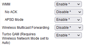
Wireless Multimedia options:
Note: Disabling WMM will/should result in clients falling back to 802.11a/g rates (54 Mbit/s).
No ACK
ACKnowledgement frames are sent on networks to acknowledge receipt of data frames. This allows applicable protocols to guarantee data delivery. However, it can also slow throughput. If acknowledgements are not necessary, and the network is reliable enough without them, disabling acknowledgements may improve throughput. Caution is advised before enabllng this setting.
APSD Mode
Automatic Power Save Delivery options:
Wireless Multicast Forwarding
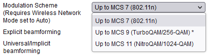
Modulation Scheme
(Note: was called Turbo QAM up to 2022.7)
This setting will enable Turbo QAM, Broadcom's name for 256-QAM. Do not confuse this with Broadcom's other Turbo QAM, a modulation scheme used for cablemodem technology. (Requires Wireless Network Mode set to Auto)
Turbo QAM, or 256-QAM is a modulation method in which the two carrier signals are shifted in phase by 90 degrees. These two signals are then modulated and combined. The 90° difference in phase between the two signals means they are “in quadrature”.
In theory, this modulation method makes it possible to transmit more bits per symbol, and thus increase data rates. In reality, most claims of big increases in transfer rates are likely exaggerated. QAM links are more susceptible to noise. As a result, Turbo QAM is generally only useful in very low-noise/interference wireless environments. Many people report it being effective on line-of-sight links of up to about 25 feet. Vendors claim the range with Turbo QAM may improve when beamforming is used. You may need to experiment to see what works best on your network.
NitroQAM/1024-QAM is only available for SDK714 Router like RT-AC5300, RT-AC3100 or RT-AC88U.
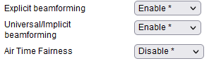
Explicit beamforming
Checking this enables Explicit beamforming technology. Traditionally, most WiFi routers and access points have included omnidirectional antennas. These radiate radio energy equally in all directions. This is not always the most effective/efficient way to exchange radio signals with a client device. Much of the signal goes off in directions other than the client or other device. Explicit beamforming improves on this.
Beamforming radiates signals towards the receiver, instead of in an omnidirectional pattern. If the hardware has adequate information to send the radio energy in one particular direction, it will do so. The result can be an increase the signal-to-noise ratio and data rates between the two devices.
Beamforming was introduced starting with 802.11n. but vendors used different standards. This meant beamforming made little difference in performance. With 802.11ac, the beamforming method was standardized (Explicit). Compatibility across vendors is good. Explicit beamforming requires both client and router/Access point to support the feature. If both devices support it, they'll use a handshake at the beginning of their session to help establish their respective locations and the channel on which they'll communicate.
Beamforming works best at medium range. At short range, the signal power is high enough that the signal-to-noise ratio will support the maximum data rate. At long ranges, beamforming does not offer gains over an omnidirectional antenna.
Universal/Implicit beamforming
Beamforming is a performance feature included in WiFi protocols starting with 802.11n. Beamforming radiates signals more directly towards the receiver, instead of in an omnidirectional pattern, like older equipment. This can result in a higher signal-to-noise ratio and faster data rates between the two devices exchanging data.
Traditionally, most WiFi routers and access points included omnidirectional antennas. These radiate radio energy equally in all directions. This is not the most effective/efficient way to exchange radio signals to another device. Much of the signal goes off in directions away from the or other wireless device.
With 802.11n, several beamforming methods were allowed, but no standard method existed. A lack of standardization meant beamforming usually provided little performance improvement.
Implicit beamforming is used with legacy devices that don't support beamforming. With Implicit beamforming, the router estimates the channel and determines the radiation direction to improve signal/transmission rate to the client device. However, it won't be able to radiate signal as precisely to the endpoint device as it could if the endpoint supported Explicit beamforming. (See above section). Implicit beamforming is also known as Universal beamforming, since it can theoretically work with almost all client equipment, even that which doesn't support beamforming.
Both access points and clients (which support it) can use beamforming. However, the higher processing power and larger distance between antennas in routers/access points means that most beamforming performance gains should be expected in transmissions from router/AP to client.
Как сделать беспроводную сеть быстрой и безопасной?
Для тех, кто не силен в особенностях современных Wi-Fi решений, отметим два важных параметра, по которым необходимо оценивать возможности беспроводного роутера, на основе которого можно просто и, главное быстро, создать достаточно сложную сеть:
- Скорость беспроводного соединения. Большинство, представленных на рынке моделей используют стандарт 802.11g, который позволяет передавать данные на скорости до 54 Mbits. Как показывает практика, этого вполне достаточно для нормальной работы, в том числе и для передачи видео потока, однако, при увеличении числа подключенных по беспроводному каналу клиентов, такое скоростное ограничение становится достаточно узким местом в вашей сети. Для решения этой проблемы, некоторые из моделей беспроводных роутеров стали использовать «расширения» стандарта 802.11g, который позволяет увеличить скорость до 108-125 Mbits. Однако увеличение скорости негативно сказалось на совместимости с устройствами, не поддерживающими скоростные «расширения». Так, например, при использовании некоторых реализаций стандарта SuperG (108 Mbits), подключить устройства, работающие на 54 Mbits, и тем более на 11 Mbits (обычно используется в КПК) у вас просто не получиться, — придется отключать «расширения».
- Безопасность. В независимости от того, где вы используете беспроводную сеть, безопасность и защищенность соединения является одним из самых важнейших вопросов. С этой точки зрения разработчики беспроводных решений потрудились на славу, обеспечив нас различными механизмами шифрования и авторизации. Так, например, введя собственный уникальный ключ а, также установив привязку всех беспроводных клиентов по MAC адресу, вы обеспечиваете довольно высокий уровень защищенности вашей сети. Однако и здесь обнаруживается недостаток, связанный с удобством, при периодическом подключении мобильных клиентов, которым вам придется постоянно напоминать используемый в вашей сети, ключ.
Именно эти две особенности, стали ключевыми при разработке новых сетевых решений Linksys, в результате чего, удалось создать производительные, защищенные, и, главное, простые в использовании, устройства, идеальным образом подходящие для создания офисной или домашней сети. Именно о таких устройствах пойдет речь в этой статье.
Особенности Ethernet роутера Linksys WRT54GS
Рассмотрение возможностей беспроводных решений Linksys мы хотели бы начать с модели WRT54GS, которая, на наш взгляд является наиболее ярким примером, предлагая нам сразу две уникальные технологии: SpeedBooster, позволяющую увеличить скорость обмена на 35% при сохранении совместимости с обычными Wi-Fi устройствами, и Secure Easy Setup, заметно облегчающую настройку сетевой безопасности для мобильных клиентов. Ниже мы более детально рассмотрим все эти особенности, а пока поговорим о конструктивных особенностях WRT54GS.

Конструктивно, роутер WRT54GS отличается от типичных представителей устройств этого класса. При первом знакомстве с WRT54GS в глаза бросается яркое двухцветное оформление корпуса, традиционное для Linksys, а также необычные ножки, обеспечивающие дополнительное охлаждение роутера, и позволяющие удобно разместить два устройства в стек. Например, вы можете разместить второй ADSL роутер WAG54G, выполняющий функции резервного канала, или многоканальный VoIP шлюз WRT54GP2, на основе которого сможете воспользоваться всеми преимуществами современной интернет-телефонии.

На лицевой панели роутера, помимо традиционных индикаторов, отображающих статус питания, WAN, LAN и WLAN соединений, имеется индикатор активности DMZ, а также необычная кнопка с логотипом Cisco Systems, Inc, которая позволяет активировать технологию Secure Easy Setup.

На тыльной стороне устройства расположены четыре порта для подключения проводных клиентов, WAN порт, для подключения внешнего сегмента, разъем для подключения блока питания, скрытая кнопка сброса и две съемные антенны, которые обеспечивают достаточно высокий коэффициент усиления, увеличивая тем самым радиус действия беспроводного сегмента.

Обращаем ваше внимание, что используемое крепление антенн несколько отличается от того, что используется в большинстве Wi-Fi устройств, что необходимо учитывать при выборе внешней антенны.
Процесс подключения WRT54GS ничем не отличается от подключения любого другого роутера. По умолчанию WRT54GS использует DHCP сервер, который заметно упрощает процесс подключения, — вам достаточно изменить параметры выбранного сетевого соединения в режим автоматической настройки, и дождаться присвоения IP адреса.
Настройка роутера может быть произведена либо с помощью Windows утилиты, либо, традиционно, с помощью продвинутого Web интерфейса, реализация которого достаточно необычна для тех из вас, кто ни раз не использовал оборудование Linksys. Однако при более детальном изучении, раскрываются некоторые из особенностей, таких как двухуровневое горизонтальное меню, а также интеллектуальная система подсказок, позволяют назвать его одним из наиболее удобных.
Процесс настройки сводится к трем основным этапам. Прежде всего, необходимо настроить параметры для внешнего сегмента WAN, для чего вы можете воспользоваться разделом Setup, где вам предлагается выбрать один из шести типов соединения с интернет. В наших условиях использовался режим автоматического конфигурирования, который получает все необходимые данные с DHCP сервера провайдера.

В случае если ваш провайдер использует привязку по MAC адресу, вам потребуется либо попросить администратора изменить используемый MAC адрес на новый, напечатанный на нижней стороне роутера, либо воспользоваться функцией клонирования MAC адреса, которая позволяет вам назначить новому устройству необходимый MAC адрес.

На следующем этапе необходимо настроить параметры внутреннего сегмента LAN и WLAN. Сначала нужно определиться, будете ли вы использовать встроенный DHCP сервер? В случае использования DHCP вы значительно облегчаете процесс подключения новых устройств, однако открываете возможность несанкционированного доступа к вашей сети извне. Для некоторых моделей беспроводных роутеров, эта особенность может стать довольно серьезной проблемой, чего мы не можем сказать о WRT54GS, но об этом чуть позже. При использовании динамического режима присвоения сетевых параметров, вы можете указать стартовый IP адрес, максимальное число клиентов, а также время доступа.
Для настройки Wi-Fi точки доступа необходимо воспользоваться разделом Wireless, который включает несколько интересных особенностей. Прежде всего, обратимся к разделу базовых настроек Wi-Fi, где вы можете изменить стандартные параметры, такие как режим, имя сети и канал связи. Обращаем ваше внимание на отсутствие возможности выбора режима SpeedBooster, или как его еще называют afterburner, позволяющим увеличить скорость беспроводного соединения на 35%. Дело в том, что в отличие от режима SuperG, afterburner активизируется автоматически, при соединении двух, поддерживающих его устройств (серия GS). Ниже мы более подробно рассмотрим особенности этого режима, а пока продолжим знакомство с особенностями настройки беспроводного модуля роутера WRT54GS, где обнаруживаем иконку статуса функции SES (Secure Easy Setup), которая является одной из двух уникальных особенностей новых роутеров Linksys.

Эта особенность была разработана совместно с компанией Broadcom, производителем чипов для Wi-Fi контроллеров. Суть SES заключается в автоматической уникальной настройке параметров беспроводного сегмента для обеспечения высочайшего уровня безопасности. Для ее активизации вам достаточно нажать на иконку, либо воспользоваться кнопкой расположенной на лицевой панели роутера. После чего программное обеспечение создаёт случайное имя SSID, отключает его трансляцию (скрывает имя сети), устанавливает безопасность WPA, генерирует пароль и передает эти параметры окружающим клиентам, поддерживающим функцию SES. В случае необходимости, вы можете произвести настройку дополнительных параметров беспроводного соединения.

По большому счету, этих двух этапов вполне достаточно для защищенного объединения компьютеров в сеть с предоставлением совместного доступа в интернет. Однако справедливости ради мы не можем не обратить внимание на встроенные функции безопасности, где Linksys есть чем похвастаться. В частности, в разделе настройки беспроводного (самого уязвимого) соединения имеется возможность выбрать один из шести режимов шифрования, и аутентификации, включая WPA2 и RADIUS.

Также имеется достаточно развитая система привязки по MAC адресу, которая поддерживает до 40 клиентов. Ее особенностью является возможность выбрать режим привязки, а также упрощенный механизм набора MAC адреса, взять который можно из списка подключенных клиентов.

Описанные выше функции безопасности относятся к защите внутреннего сегмента от стороннего вторжения, что же касается защиты от вторжений из интернет, то в этом вопросе, WRT54GS оснащен достаточно мощным межсетевым экраном с гибкими возможностями перенаправления до 10 портов, активизации DMZ, а также создания расписания работы.

Проверить правильность настройки можно в разделе Status, где также сможете произвести обновление параметров соединения.

Разобравшись с особенностями настройки и конфигурирования роутера Linksys WRT54GS, пришло время посмотреть, на что же способна, используемая в нем технология afterburner, которая позволяет на 35% увеличить скорость беспроводного соединения, что в современных условиях очень актуально. Итак, для изучения возможностей роутера WRT54GS мы использовали Wi-Fi карта WMP54GS, поддерживающую технологию afterburner, и простой, встроенный в ноутбук Wi-Fi контроллер, поддерживающий стандарт 802.11g. В результате мы увидели следующие цифры.
При использовании режима afterburner, мы видим обещанные 35% прироста, что, честно говоря, несколько удивляет. Обычно, данные от производителя сильно завышены, чего мы не можем сказать о Linksys. Более того, данные были получены на расстоянии около 100 метров в прямой видимости. На более коротких расстояниях нам удалось увидеть увеличение скорости до 46%. Кроме этого, важно отметить, что при параллельном подключении обычных и afterburner клиентов, не возникает проблем совместимости, просто скорость снижается примерно до 26 Mbits, что лично нас более чем устраивает. По сравнению с SuperG, которая позволяет добиться 46Mbit, afterburner явно проигрывает, однако, учитывая отсутствие проблем, совместимость с различными типами оборудования делает ее более интересной при использовании в неоднородных сетях.
Особенности ADSL роутера Linksys WAG54G…
Второй беспроводной роутер, который мы хотим рассмотреть в этой статье, Linksys WAG54G, относится к устройствам предыдущего поколения, и представляет собой ADSL роутер, который мы используем в качестве резервного интернет канала. Выбор именно этой модели не случаен, и основан, прежде всего, на конструктивных особенностях. Помимо удобных ножек, в конструкции этих двух роутеров, обнаружилась еще одна интересная особенность, а именно, длинна поворотного механизма антенн у WRT54GS несколько больше, чем у WAG54G, что позволило без проблем собрать их в такую своеобразную стойку. Кроме того, этот роутер идеально подходит для подключения к СТРИМ.

Как вы уже поняли конструктивно, Linksys WAG54G практически не отличается от WRT54GS, — разница заключается в реализации лицевой и тыльной сторон роутера. На лицевой стороне роутера размещается несколько более простая панель управления, включающая традиционные индикаторы питания и активности LAN портов и WLAN соединения. Кроме этого, здесь имеются два дополнительных индикатора, отображающих статус DSL соединения и активность PPPoE, т.е. доступность интернета.

Тыльная сторона выполнена вполне традиционно, за исключением использования только одной антенны, и дополнительного выключателя питания.

Подключить Linksys WAG54G достаточно просто, и мы не хотели бы подробно останавливаться на этом вопросе, и перейдем сразу к особенностям настройки. Единственное, обращаем ваше внимание, на отсутствие в комплекте поставки специального фильтра, позволяющего устранить неприятный высокочастотный сигнал в трубке параллельного телефона. Мы использовали стандартный фильтр, который можно купить в любом компьютерном рынке.

Процесс настройки Linksys WAG54G практически не отличается от WRT54GS, за исключением некоторых специфических функций, как, например, установка ADSL соединения. Здесь WAG54G предлагает самые разнообразные варианты, однако, для большего удобства используем PPPoE. В этом режиме необходимо ввести имя соединения, логин и пароль, предоставленные вашим провайдером, и, при необходимости, изменить некоторые специальные параметры. Для проверки, и управления соединением (необходимая вещь в любом ADSL роутере), можно воспользоваться разделом STATUS.

Что же касается особенностей настройки Wi-Fi и встроенного межсетевого экрана, то здесь WAG54G не отличается от WRT54GS, поэтому мы не будем тратить время, и перейдем сразу к результатам тестов, где нас интересовали два основных вопроса: качество ADSL соединения и скорость беспроводного канала. По всем этим параметрам Linksys WAG54G оказался вполне типичным устройством, не хуже и не лучше других, представленных на рынке решений. На не очень качественной линии 6144 Kbits, WAG54G показал результат 5120 Kbits, при этом стабильность соединения была довольно высока, что позволило нам рекомендовать его для использования в круглосуточном режиме. Что же касается скорости соединения по беспроводному каналу, то здесь мы наблюдаем те же 24-25Mbits в секунду, причем в независимости от удаленности клиента от точки доступа.
Заключение
Если, рассмотренный только что ADSL роутер Linksys WAG54G не имеет каких-либо уникальных особенностей, и от других отличается лишь удобным интерфейсом и продвинутым межсетевым экраном, обеспечивающим надежную защиту вашей внутренней сети, от внешних вторжений, то модель WRT54GS оказалась более, чем интересной, предлагая нам достаточно универсальное решение по созданию быстрой и безопасной сети, и совместимой с различными типами устройств, что для нас, является одним из важнейших вопросов.
Advanced wireless settings
Before reading this page please be familiar with Basic Wireless Settings.
This page contains more robust explanations of Advanced Wireless Settings than the built in help provides. It was originally authored by Stephen Suley in this thread. Note, this is mainly for Broadcom Routers.
See QCA wireless settings page for specific info for Qualcomm Atheros advanced settings.
[edit] Advanced Wireless Settings
[edit] Authentication Type
Available Settings: Auto, Shared Key
Default Setting: Auto
Recommended Setting: Auto
The help file says. * Allows either Open System or Shared Key authentication to be used. For Open System authentication, the sender and the recipient do NOT use a WEP key for authentication. For Shared Key authentication, the sender and recipient use a WEP key for authentication. If you want to use only Shared Key authentication, then select Shared Key.
How it works:
The following steps occur when two devices use Shared Key Authentication:
- The client adapter sends an authentication request to the access point.
- The access point sends back a challenge text to the client adapter.
- The client uses its configured 64-bit or 128-bit default key to encrypt the challenge text, and it sends the encrypted text to the access point.
- The access point decrypts the encrypted text using its configured WEP key that corresponds to the client’s default key. The access point compares the decrypted text with the original challenge text. If the decrypted text matches the original challenge text, then the access point and the client share the same WEP key, and the access point authenticates the client.
- The client will now connect to the network.
If the decrypted text does not match the original challenge text (that is, the access point and station do not share the same WEP key), then the access point will refuse to authenticate the station, and the station will be unable to communicate with either the 802.11 network or Ethernet network.
-This would add an additional layer of connection authentication for wireless clients. Using this feature means you must modify the wifi adapter settings on a client before it can connect to this device.
-Client wifi adapters must support «Shared Key» authentication to use this setting.
-If using a client connected to the router over wireless and you set authentication key to shared, from auto, and your computer doesn’t support shared, you will lose all Internet access and access to the webgui and you will have to connect with a wire to the router to change the setting back to auto. You can also do a hard reset to get it back to defaults to fix this.
-I equate using «Shared key» to adding authentication security to the «Phase 1» of the wifi connection process
-Changing this from the default value would be for security reasons.
[edit] Basic Rate
Available Settings: Default, 1-2Mbps, all
Default Setting: Default
Recommended Setting: Default
The help file says. * Depending on the wireless mode you have selected, a default set of supported data rates will be selected. The default setting will ensure maximum compatibility with all devices. You may also choose to enable all data rates by selecting ALL. For compatibility with older Wireless-B devices, select 1-2Mbps.
How it works:
[edit] MIMO — Transmission Fixed Rate
Available Settings: Auto, a range of values from 6.5Mbps upwards
Default Setting: Auto
Recommended Setting: Auto
The help file says.
- The idea is the same as «Transmission Fixed Rate» You can select from a range of MIMO transmission speeds, or keep the default setting, Auto, to have the router automatically use the fastest possible data rate and enable the Auto-Fallback feature. Auto-Fallback will negotiate the best possible connection speed between the router and a wireless client.
How it works:
This parameter is used for 802.11n transmissions only. 802.11a/b/g transmissions from the router use the «Transmission Fixed Rate» parameter.
IEEE 802.11n builds on previous 802.11 standards by adding multiple-input multiple-output (MIMO). MIMO uses multiple transmitter and receiver antennas to improve the system performance. MIMO is a technology which uses multiple antennas to coherently resolve more information than possible using a single antenna. Two important benefits it provides to 802.11n are antenna diversity and spatial multiplexing. MIMO technology relies on multipath signals. Multipath signals are the reflected signals arriving at the receiver some time after the line of sight (LOS) signal transmission has been received. MIMO uses the multipath signal’s diversity to increase a receiver’s ability to recover the message information from the signal.
Another ability MIMO technology provides is Spatial Division Multiplexing (SDM). SDM spatially multiplexes multiple independent data streams, transferred simultaneously within one spectral channel of bandwidth. MIMO SDM can significantly increase data throughput as the number of resolved spatial data streams is increased. Each spatial stream requires a discrete antenna at both the transmitter and the receiver. In addition, MIMO technology requires a separate radio frequency chain and analog-to-digital converter for each MIMO antenna which translates to higher implementation costs compared to non-MIMO systems.
[edit] Transmission Fixed Rate
Available Settings: Auto, range from 1 to 54 Mbps
Default Setting: Auto
Recommended Setting: Auto
The help file says. * The rate of data transmission should be set depending on the speed of your wireless network. You can select from a range of transmission speeds, or keep the default setting, Auto, to have the router automatically use the fastest possible data rate and enable the Auto-Fallback feature. Auto-Fallback will negotiate the best possible connection speed between the router and a wireless client.
How it works:
[edit] CTS Protection mode
Available Settings: Auto, Disabled
Default Setting: Auto
Recommended Setting: Auto
The help file says. * When set to Auto, a protection mechanism will ensure that your Wireless-B devices will connect to the Wireless-G router when many Wireless-G devices are present. However, performance of your Wireless-G devices may be decreased.
How it works:
CTS Protection mode is a protection mechanism that operates on the physical (PHY) level frame. At a very high level summary of the process when multiple devices are connected to an access point, they can occasionally be transmitting data to the access point at the same time because neither one can see the other client well enough to determine if it is transmitting on the channel or not. When this happens, the AP will discard both pieces of colliding data, thus contributing to error rates. CTS (clear to send) protection skirts this issue by delegating which device gets to transmit at a given time.
CTS Protection mode and DD-wrt:
In its default configuration dd-wrt uses it as a to provide a way of ensuring coexistence between the legacy and the new wifi devices. Adding to that by using CTS protection mode and modifying RTS threshold value you can tweak the operation of the CTS protection mechanism this can then be combined with the Fragmentation Threshold tweak to help troubleshoot\fix connectivity and\or performance issues etc. Remember tweaking the CTS protection process by manipulating the RTS and the Fragmentation Threshold value often comes at a price usually by decreasing the overall throughput to the WLAN.
Once CTS Protection mode is configured correctly within your WLAN environment there are specific scenarios that occur and the software will activate the CTS protection mechanisms;
Here are a few examples of what triggers CTS to be employed by the dd-wrt router software.
CTS Protection trigger 1; — NON-default dd-wrt behavior A client that wants to use the radio channel to send data packet(s) of a size that is equal or above the defined RTS threshold value.
CTS Protection trigger 2; -default dd-wrt behavior A 802.11g client attempts to connect to a SSID that is using channel bonding. Transmissions using a 40 MHz channel in the presence of 802.11a or 802.11g clients require using CTS protection mode. This will apply the CTS protection mechanism on both 20 MHz halves of the 40 MHz channel, to prevent interference with legacy devices and allow proper operation of the 802.11a and 802.11g clients.
CTS Protection trigger 3; -default dd-wrt behavior If you are running in mixed wireless mode on a 802.11n router and you have 802.11b clients in your environment. CTS Protection is used to allow the 802.11b client to operate correctly and also not to interfere with the operation of the 802.11a,g, and N client transmissions.
Also; — An 11b device associates to the AP. — same as trigger 3 — An 11b AP on the same channel can be heard by the AP — variant on trigger 3 — The AP hears an 11g AP that is in protection because of an 11b device associated. -another variation of the trigger 3 event.
NOTE: Trigger 1 will never happen on the dd-wrt default configuration due to the default values of the RTS Threshold being 2347 and the Fragmentation Threshold value being 2346. Based on the data packet fragmentation threshold default value at 2346 in size dd-wrt will apply fragmentation to all packets meeting this criteria. Because of this fragmentation process the 2347 packet size needed to trigger the RTS threshold is never reached.
For a closer look at what happens in one of these cases lets look at a case like trigger number 1 list above and the steps in the CTS protection process.
Example. A client that wants to use the radio channel to send data packet(s) of a size that is equal or above the defined RTS threshold value.
Steps in the CTS Protection mode process for the above example.
1.) The client wishing to send date over the channel first sends an RTS (request to send) packet to the AP.
2.) As the AP broadcast it beacons packet over the WLAN as part of its normal operation, The beacon packet has information within it that declares to all the clients on the entire WLAN not to try and send any information for a specified period of time. The AP then sends a CTS packet to the client that requested the CTS in the first place. The AP has made a single client the «owner» of the wifi channel and then the AP listens only to that client until it is done transmitting; its in protection mode.
3.)The process is repeated for all request to transfer data,which for whatever reason triggers the CTS protection mechanisms, on a first come first serve basis.
TWEAK: Implementing additional CTS Protection mode triggers and there frequency of operation on top of the default dd-wrt CTS protection mode configuration;
1.) The AP running dd-wrt has the CTS Protection mode is set to Auto by default and then you could adjust the RTS threshold value to something lower then 2346 (Which is the default fragmentation threshold value on dd-wrt) on the AP.
2.) All clients connected to the dd-wrt AP are configured for CTS\RTS mode as apposed to setting of «disabled» or «CTS-Self» mode.
NOTE Typically the The RTS Threshold value on dd-wrt is only lowered when needed to address or troubleshoot some sort of connectivity or performance issue with a client or all clients on a WLAN. Adjusting the value is a balancing act between getting your problem fixed and losing overall WLAN speed. The more times CTS protection mode is triggered in a period of time «its frequency» the more impact it will have; good or bad. So start with 2340, then 2320, 2300 etc.
Guide when to use and why.
-If your trying to tweak out every drop of performance in an ideal setup then you can disable this on the AP and clients. Test again to see if it helps for better results, it should.
-If you want to try 40MHz with your 802.11n clients you might want to start with CTS Protection set to Auto. You do this in case you have 802.11a or g or even some N clients that do not support 40GHz transmissions or «channel bonding» as it is sometimes called.
-If you have a 802.11n based router running in mixed wireless mode that you want to connect 802.11b clients you need to have CTS protection mode set to Auto meaning enabled.
-If CTS Protection makes things faster a network redesign might be needed.
-«CTS to self» based protection — an alternate implementation method of CTS; where by the device willing to send frames over the WLAN first sends a CTS frame to itself. «CTS to self» based protection has less overhead, but it must be taken into account that this only protects against devices receiving CTS frame (e.g. if there are 2 «hidden» stations, there is no use for them to use «CTS to self» protection, because they will not be able to receive CTS sent by other station — in this case stations must use RTS/CTS so that other station knows not to transmit by seeing CTS transmitted by AP).If you have set the CTS protection mode to disabled on the dd-wrt AP, then this is a good choice for the client configuration.
[edit] Frame Burst
Available Settings: Enable, Disable
Default Setting: Disable
Recommended Setting: Disable
The help file says.
- Frame burst allows packet bursting which will increase overall network speed though this is only recommended for approx 1-3 wireless clients, Anymore clients and there can be a negative result and throughput will be affected.
How it works:
Frame-bursting is a technique in wireless technology supported by the draft 802.11e Quality of Service specification. Frame Bursting may increase the throughput of any (point-to-point) 802.11A, B, G or N link connection in certain conditions. This is done by reducing the overhead associated with the wireless session from either: * Access Point to Client and vice versa
- Client to Client in ad-hoc mode.
This can result in the ability to support higher data throughput in mixed and uniform networks.
It enhances the ability of a wireless client to upload data at faster speeds by using the inter-frame wait intervals to «burst» a sequence of up to three packets before waiting the required period. This allows more data to be sent and less waiting to occur, however, can result in unfair allocation of airtime where there are a mix of clients of which only some support Frame-Bursting as the inter-frame wait periods are contention periods where other stations with data to send can seize the air and send their data.
-Frame Burst is useful when transferring large data, but the benefits are not as big as most people hope for.
-It allows, as name says, a client to burst many frames in a short amount of time.
[edit] Beacon Interval
Available Settings: range from 10 to 65535 ms
Default Setting: 100 ms
Recommended Setting: 50
300 for 2.4 GHz & 75
The help file says. * The Beacon Interval value indicates the frequency interval of the beacon. A beacon is a packet broadcast by the router to synchronize the wireless network. 50 is recommended in poor reception.
How it works:
The term beacon signifies a specific data transmission from the wireless access point (AP), which carries the SSID, the channel number and security protocols such as WEP (Wired Equivalent Protection) or WPA (Wi-Fi Protected Access). This transmission does not contain the link layer address of another Wi-Fi device, therefore it can be received by any LAN client.The beacon frame, which is a type of management frame, can be likened with the «heartbeat» of a wireless LAN, enabling stations to establish and maintain communications in an orderly fashion.
What is a Beacon Interval As mentioned above, the beacon interval is a fixed, configurable parameter. Typically, the beacon interval setting is not touched at all in the WLAN network installation phase, but the default value selected by the equipment supplier is used. If the beacon interval is long, maximum capacity in the Access Point is achieved. However, it will the take a long time for WLAN terminals to scan for Access Points in the area and to update RSSI and load information for already found Access Points. This obviously reduces terminal throughput and wastes battery. On the other hand, if the beacon interval in short, passive scanning performed by the WLAN terminals will be faster, but the overall capacity of the Access Point will be reduced.
NOTE There are no special rules for sending beacons, and they must be sent using the mandatory 802.11 carrier sense multiple access / collision avoidance (CSMA/CA) algorithm. If another station is sending a frame when the beacon is to be sent, then the access point (or NIC in an ad hoc network) must wait. As a result, the actual time between beacons may be longer than the beacon interval. Clients, however, compensate for this inaccuracy by utilizing the timestamp found within the beacon packet information.
What is a Beacon?
A typical beacon frame is approximately fifty bytes long, with about half of that being a common frame header and cyclic redundancy checking (CRC) field. As with other frames, the header includes source and destination MAC addresses as well as other information regarding the communications process. The destination address is always set to all ones, which is the broadcast Medium Access Control (MAC) address. This forces all other stations on the applicable channel to receive and process each beacon frame. The CRC field provides error detection capability.
The beacon’s frame body resides between the header and the CRC field and constitutes the other half of the beacon frame. Each beacon frame carries the following information in the frame body:
Beacon interval. This represents the amount of time between beacon transmissions. Before a station enters power save mode, the station needs the beacon interval to know when to wake up to receive the beacon (and learn whether there are buffered frames at the access point).
Timestamp. After receiving a beacon frame, a station uses the timestamp value to update its local clock. This process enables synchronization among all stations that are associated with the same access point.
Service Set Identifier (SSID). The SSID identifies a specific wireless LAN. Before associating with a particular wireless LAN, a client must have the same SSID configured as the access point. By default, access points include the SSID in the beacon frame to enable sniffing functions (such as that provided by Windows XP) to identify the SSID and automatically configure the wireless network interface card (NIC) with the proper SSID. DD-Wrt also has an option to disable the SSID from being broadcast in beacon frames to reduce security issues.
Supported rates. Each beacon carries information that describes the rates that the particular wireless LAN supports. For example, a beacon may indicate that only 1, 2, and 5.5Mbps data rates are available. As a result, an 802.11b station would stay within limits and not use 11 Mbps. With this information, stations can use performance metrics to decide which access point to associate with.
Parameter Sets. The beacon includes information about the specific signaling methods (such as frequency hopping spread spectrum, CTS Protection mode and RTS Threshold,direct sequence spread spectrum, etc.). For example, a beacon would include in the appropriate parameter set the channel number that an 802.11b access point is using. Likewise, a beacon belonging to frequency hopping network would indicate hopping pattern and dwell time.
Capability Information. This signifies requirements of stations that wish to belong to the wireless LAN that the beacon represents. For example, this information may indicate that all clients must use wired equivalent privacy (WEP) in order to participate on the network.
Traffic Indication Map (TIM). An access point periodically sends the TIM within a beacon to identify which stations using power saving mode have data frames waiting for them in the access point’s buffer. The TIM identifies a station by the association ID that the access point assigned during the association process.
NOTE Today beacon frames also contain a load information that informs WLAN terminals currently connected to a specific Access Point or considering making a handover to that Access Point about the load situation. This information helps the WLANterminals in making correct handover decision, in addition to the information from the comparisons of RSSI readings obtained by scanning, and thus ensures that WLAN traffic is divided more evenly between all Access Points in the area.
By increasing the beacon interval, you can reduce the number of beacons and associated overhead, but that will likely delay the association and roaming process because stations scanning for available access points may miss the beacons.
You can decrease the beacon interval, which increases the rate of beacons. This will make the association and roaming process very responsive; however, the network will incur additional overhead and throughput will go down.
In addition, stations using power save mode will need to consume more power because they’ll need to awaken more often, which reduces power saving mode benefits. In an idle network, beacons dominate all other traffic.
Guide to tweaking: The amount of overhead that the transmissions of beacon frames generate is substantial; however, the beacon serves a variety of functions. For example, each beacon transmission identifies the presence of an access point.
How a beacon interval impacts the client By default, radio NICs passively scan all RF channels and listen for beacons coming from access points in order to find a suitable access point. When a beacon is found, the radio NIC learns a great deal about that particular network. This enables a ranking of access points based on the received signal strength of the beacon, along with capability information regarding the network. The radio NIC can then associate with the most preferable access point. After association, the station continues to scan for other beacons in case the signal from the currently-associated access point become too weak to maintain communications. As the radio NIC receives beacons from the associated access point, the radio NIC updates its local clock to maintain timing synchronization with the access point and other stations. In addition, the radio NIC will abide by any other changes, such as data rate, that the frame body of the beacon indicates. The beacons also support stations implementing power saving mode. With infrastructure networks, the access point will buffer frames destined for sleeping stations and announce which radio NICs have frames waiting through the TIM (DTIMS) that’s part of the beacon
Do clients send beacon frames too. As apposed to beacons sent out by AP’s, Clients send out «probe request» frames; It’s like an opposite to a beacon, clients use a probe request packets to play there role in the 802.11 WLAN. An 802.11 probe response frame is very similar to a beacon frame, except that probe responses don’t carry the TIM info and are only sent in response to a probe request. A client may send a probe request frame to trigger a probe response when the client needs to obtain information from another client on the same WLAN. A client, for instance, will broadcast a probe request when using active scanning to determine which access points are within range for possible association. Some sniffing software (e.g., NetStumbler) tools send probe requests so that access points will respond with desired info.
-Beacons are packets sent by an access point to synchronize a wireless network.
-Normal Traffic Indication Message(TIM)s that are present in every beacon are for signaling the presence of unbuffered unicast data.
[edit] DTIM Interval
Available Settings: range from 1 to 255
Default Setting: 1
Recommended Setting: 1 (assuming default beacon interval of 100 is used)
The help file says. * Indicates the interval of the Delivery Traffic Indication Message (DTIM). A DTIM field is a countdown field informing clients of the next window for listening to broadcast and multicast messages. When the router has buffered broadcast or multicast messages for associated clients, it sends the next DTIM with a DTIM Interval value. Its clients hear the beacons and awaken to receive the broadcast and multicast messages.
How it works:
A Delivery Traffic Indication Message is a kind of Traffic Indication Message(TIM) which informs the clients about the presence of buffered and/or multicast/broadcast data on the access point. It is generated within the periodic beacon at a frequency specified by the DTIM Interval. After a DTIM, the access point will send the multicasted/broadcasted data on the channel following the normal channel access rules (CSMA/CA).
According to the 802.11 standards, a Delivery Traffic Indication Message (DTIM) period value is a number that determines how often a beacon frame includes a Delivery Traffic Indication Message, and this number is included in each beacon frame. A DTIM is included in beacon frames, according to the DTIM period, to indicate to the client devices whether the access point has buffered broadcast and/or multicast data waiting for them. Following a beacon frame that includes a DTIM, the access point will release the buffered broadcast and/or multicast data, if any exists.
Since beacon frames are sent using the mandatory 802.11 carrier sense multiple access/collision detection (CSMA/CD) algorithm, the access point must wait if a client device is sending a frame when the beacon is to be sent. As a result, the actual time between beacons may be longer than the beacon interval. Client devices that awaken from power-save mode may find that they have to wait longer than expected to receive the next beacon frame. Client devices, however, compensate for this inaccuracy by utilizing the time-stamp found within the beacon frame.
The 802.11 standards define a power-save mode for client devices. In power-save mode, a client device may choose to sleep for one or more beacon intervals waking for beacon frames that include DTIMs. When the DTIM period is 2, a client device in power-save mode will awaken to receive every other beacon frame. Upon entering power-save mode, a client device will transmit a notification to the access point, so that the access point will know how to handle unicast traffic destined for the client device. The client device will begin to sleep according to the DTIM period.
-The higher the DTIM period, the longer a client device may sleep and therefore the more power that particular client device may potentially save.
-Client devices in wireless networks may have conflicting requirements for power consumption and communication throughput when in power-save mode. For example, laptops may require relatively high communication throughput and may have low sensitivity to power consumption. Therefore, a relatively low DTIM period, for example 1, may be suitable for laptops . However, cellphones may require relatively low communication throughput and may be operated by batteries of relatively low capacity. Therefore, a relatively high DTIM period, for example 8, may be suitable for cellphones. Further, PDA\Smart phones may require a medium to high communication throughput and may be operated by batteries of relatively low capacity. Therefore, a medium DTIM period, for example a value of 4, may be suitable for these devices.
-Currently, an access point is able to store only a single DTIM period. Consequently, different client devices in power-save mode will all wake up for the same beacon frames according to the DTIM period. Currently, a network manager may need to balance the conflicting requirements for power consumption and communication throughput when in power-save mode of client devices in different wireless networks when configuring the DTIM period of an access point. In the future an access point with support for two or more SSIDs may have SSID-dependent DTIM periods rather than a single DTIM period for all SSIDs. In other words, the network manager may configure the access point with DTIM periods on a per SSID basis. A network manager may consider the requirements of power consumption and communication throughput of client devices in a particular wireless networks when determining which DTIM period to configure for which SSID. A higher DTIM period may increase the potential savings in power consumption but may reduce the communication throughput, and vice versa
[edit] Fragmentation Threshold
Available Settings: range from 256 to 2346
Default Setting: 2346
Recommended Setting: 2346
The help file says. * It specifies the maximum size for a packet before data is fragmented into multiple packets. If you experience a high packet error rate, you may slightly increase the Fragmentation Threshold. Setting the Fragmentation Threshold too low may result in poor network performance. Only minor modifications of this value are recommended.
How it works:
The Threshold for fragmentation to occur is a 802.11 configuration parameter. This is an optional feature, the 802.11 standard and dd-wrt includes the ability for access points to fragment packets for improving performance in the presence of RF interference and marginal coverage areas
To use fragmentation means to divide 802.11 frames into smaller pieces (fragments) that are sent separately to the destination. Each fragment consists of a MAC Layer header, frame check sequence (FCS), and a fragment number indicating its ordered position within the frame. Because the source transmits each fragment independently, the receiving destination replies with a separate acknowledgement for each fragmen
-Fragmentation only applies to frames having a unicast (address assigned to a single host on your network) receiver address.
-The use of fragmentation can increase the reliability of frame transmissions. Because of sending smaller frames, collisions are much less likely to occur.
-Similar to RTS, a good method to find out if you should activate fragmentation is to monitor the wireless LAN for collisions. If you find a relatively large number of collisions, then try using fragmentation. This can improve throughput if the fragmentation threshold is set just right.
-try setting the fragmentation threshold to around 800 bytes first, then tweak it until you find the best results.
-As with any 802.11 tuning mechanisms, the goal is to improve performance.
-If what you do improves throughput, then you’re doing the right thing.
-If hidden nodes are present the use of RTS and\or CTS could be a better way to reduce collisions.
[edit] RTS Threshold
Available Settings: range from 0 to 2347
Default Setting: 2347
Recommended Setting: 2347
The help file says. * The router sends Request to Send (RTS) frames to a particular receiving station and negotiates the sending of a data frame. After receiving an RTS, the wireless station responds with a Clear to Send (CTS) frame to acknowledge the right to begin transmission.
How it works:
The RTS Threshold value is a configurable parameter within the CTS Protection mechanism. The RTS threshold is used as a trigger to engage the back and forth of RTS and CTS messages between AP and client. The triggers purpose is a type of handshaking approach that provides and additional layer of control over the use of the shared medium, or in the case of DD-WRT the Radio Channel or WLAN. If enabled, A node (client) wishing to send data initiates the process by sending a Request to Send frame (RTS).
How the RTS Threshold value works in DD-WRT. As discussed in the CTS Protection mode section of this document, when a packet that a DD-WRT access point is transmitting is larger than the RTS threshold set in the configuration, DD-WRT will initiate the CTS Protection mode handshaking function. If the network packet being sent is smaller or fragmented to a size lower than the preset RTS threshold size, the CTS Protection mode mechanism will still not be enabled for that packet. Note if the packet size happens to be equal to the threshold, DD-WRT will not use CTS.
Tweak: In DD-WRT, the default configuration after a flash sets the CTS Protection mode not to get triggered to protect transmissions by RTS. This is due to the fact that Sending RTS frames is turned off by default (threshold >=2347bytes). If the packet size the node wants to transmit is larger than the threshold, the RTS/CTS handshake gets triggered. If the packet size is equal to or less than threshold the data frame gets sent immediately.
The method for enabling RTS-CTS triggers on DD-WRT is different than with client NICs. For DD-WRT, you enable RTS-CTS handshaking triggers within WebGUI by setting a specific packet size threshold (0 — 2347 bytes) in the user configuration interface; only minor modifications are recommended.
Set this value to a 2340 bytes as a start, test, then if needed try a lower value, etc.
Save. Apply. Reboot.
Rollback Set the value back to its default value of 2347 bytes and disable RTS threshold triggers in the CTS Protection mode operation on the router.
[edit] Max Associated Clients
Available Settings: range from 1 to 256
Default Setting: depends on the router, usually 128
Recommended Setting: What ever you want
The help file says. *
How it works:
This number will determine how many clients can be connected to the routers wireless LAN (WLAN)
[edit] AP Isolation
Available Settings: Enable, Disable
Default Setting: Disable
Recommended Setting: Disable for private home Wi-Fi with trusted users, enable for public/guest Wi-Fi hotspot
The help file says. * This setting isolates wireless clients so access to and from other wireless clients are stopped.
How it works:
Wireless access points work by bridging the wireless port to the wired switch ports and router port. Everything happens at the MAC address level and does not involve IP addresses,NETBIOS over TCP/IP (also known as MS Networking). Just MAC addresses.
The wireless bridge builds a bridging table consisting of a table of «heard» (or sniffed) MAC addresses that appear on various ports. Think of the router having just 3 available ports; Wireless, Ethernet switch, and router port. If the destination MAC address of a port is shows up in the MAC address table as sitting on a specific port, only that port gets the traffic. Broadcasts, which have no destination MAC address are sent to all ports.
When this feature is enabled the software builds a logical rule (or filter) for these MAC addresses and ports that says:
«If the packet originates on the wireless port, it can only send and receive packets that are destined or originate from the router port or ethernet switch port.»
Not a very complex rule, but one which totally prevents wireless client to client traffic. Not even broadcasts will go from wireless client to client.
-prevents one wireless client communicating with another wireless client.
-This breaks the connection between WLAN and WLAN
-No improvement in performance, performance is exactly the same. The difference is in «reliability» or ability to survive in a multi-path environment.
-You enable this if you are running a hotspot. Click Network Neighborhood in a motel sometime, see if the motel needs to set AP isolation.
-Changing this from the default value would be for security reasons.
[edit] TX Antenna / RX Antenna
Available Settings: 1, 1+2, 1+3, 1+2+3, 1+2+3+4 (varies by router)
Default Setting: Varies by router
Recommended Setting: Varies by router
This setting is critical for proper, smooth, fast Wi-Fi performance. 2×2:2 routers will either have TX/RX chains at 1+2/1+2, 1+3/1+3, 1+2/1+3, or 1+3/1+2. This can take some time to find the proper setting but its worth it, you can more easily find the correct setting by using a 802.11n client thats capable of 300 Mbps link. Note the TX/RX link rates on the wireless status page, when set incorrectly one or both of the rates will drop to a much lower speed such as 200, 170, 81 etc. This is best done with the client less than 10 feet from the AP with clear line of sight. Some routers with chains set incorrectly such as D-Link DIR-615 C1, will deny connections to clients, heavily reduce throughput, and other errors. Searching the FCC ID of your router will aid in setting the correct chain settings. Some popular routers such as the Netgear WNDR3700 v1/2/4 and D-Link DIR-825 B1/B2 require both chains set at 1+2 for proper Wi-Fi performance. Default is not always right!*
* With builds around r21061 or later, most units have the proper defaults preset & invalid options removed, such as 1+2+3 for TX/RX on WNDR3700 v1, v2, & v4 as the router only has 2 chains each therefor only has 1 & 1+2 available to be selected. While a Asus N66U have 1+2+3 as they are 3×3:3 units. An example 4×4:4 unit is the R7800.
* The option may have disappeared in recent builds (>336XX).
The help file says. * This is used in conjunction with external antennas to give them optimum performance. On some router models left and right antennas may be reversed depending on you point of view.
How it works:
This value determines which Antenna connection is used for the purposes of Rx and Tx functions.
[edit] Preamble
Available Settings: Short, Long, Auto
Default Setting: Long
Recommended Setting: Short
The help file says. * If your wireless device supports the short preamble and you are having trouble getting it to communicate with other 802.11b devices, make sure that it is set to use the long preamble.
How it works:
The preamble is used to communicate to the receiver that data is on its way. Technically speaking, it is the first portion of the Physical Layer Convergence Protocol/Procedure (PLCP) Protocol Data Unit (PDU). The preamble allows the receiver to acquire the wireless signal and synchronize itself with the transmitter. A header is the remaining portion and contains additional information identifying the modulation scheme, transmission rate and length of time to transmit an entire data frame.
Long Preamble: * Compatible with legacy IEEE* 802.11 systems operating at 1 and 2 Mbps (Megabits per second)
- PLCP with long preamble is transmitted at 1 Mbps regardless of transmit rate of data frames
- Total -Long Preamble transfer time is a constant at 192 usec (microseconds)
Short Preamble: * Not compatible with legacy IEEE 802.11 systems operating at 1 and 2 Mbps -PLCP with short preamble: Preamble is transmitted at 1 Mbps and header at 2 Mbps — -Total Long Preamble transfer time is a constant at 96 usec (microseconds)
- Unless you have 802.11b (1 or 2Mbits/sec) client radios in your system, there’s no need for a long preamble. The default for most access points is «automatic». It only enables long preambles when associated with a 1 or 2Mbit/sec client radio.
- Most access points (AP) and broadband WiFi routers are configured for a Long Preamble or have a setting that automatically detects the preamble and adjusts accordingly. A majority of client WiFi adapters should also be pre-configured in the same manner. This is done as a precautionary measure for networks that may still employ legacy devices.
[edit] Shortslot Override
Available Settings: Short, Long, Auto
Default Setting: Auto
Recommended Setting: Short
The help file says. *
How it works:
Short Slot Times — The amount of time a device waits after a collision before retransmitting a packet. You can increase throughput on 802.11g, 2.4-GHz radios by enabling Shortslot override (most .11g radios enable this by default). Reducing the slot time from the standard 20 microseconds to the 9-microsecond short slot time decreases the overall backoff, which increases throughput. Backoff, which is a multiple of the slot time, is the random length of time a station waits before sending a packet on the LAN.
Many 802.11g radios support Shortslot override, but some do not. When Shortslot override is enabled, the wireless device uses the short slot time only when all clients associated to the 802.11g, 2.4-GHz radio support Shortslot override. Shortslot override is an 802.11g-only feature and does not apply to 802.11a radios.
SUMMARY: Slot times should transition from 20us to 9us when a «pure» .11g environment exists for that AP. Also applies to NG networks.
[edit] TX Power
Available Settings: Auto or Manual
Default Setting: Auto
Recommended Setting: Auto, unless you know what you are doing.
Atheros and others:
Available Settings: 0
Default Setting: 16
30 dBm (varies by router)
Recommended Setting: Highest dBm your radios & local laws legally allow**
-
- Recommended Setting
Some people believe that «high» TX power (i.e., greater than 25 dBm), may be of concern to one’s health. That is not the case but each to their own. So if that’s you then 22 — 25 dBm should be sufficient; any lower & range starts to significantly drop (unless you want to of course & if you have an older router than only does something like 18 dBm, no need). In case you are wondering, every 3 dBm is doubled the power, so 13 dBm is twice as much as 10 dBm, & so on; but don’t worry, 30 dBm is only 1 watt.
The help file says. * A safe increase of up to 70 would be suitable for most users. Higher power settings are not recommended for users due to excess heat generated by the radio chipset, which can affect the life of the router.
How it works:
The milliwatt (symbol:mW) is equal to one thousandth (10-3) of a watt. A typical laser pointer might output 5 milliwatts.
This setting will determine the number of milliwatts used to power the radio signal output from the router.
- Linksys ships out their units with the TX power set to 28 mW by default.
- mW \ Dbm Power Conversion Table
- mW — 1 2 3 4 5 6 8 10 12 15 20 25 30 40 50 60 80 100
- DBm -1 2 5 6 7 8 9 10 11 12 13 14 15 16 17 18 19 20
How to convert dBm to mW
The power conversion of dBm to mW is given by the formula:
P(mW) = 10 ^ (P(dBm) / 10)
So .. 1dBm = 1.258925mW
How to convert mW to dBm
The power conversion of mW to dBm is given by the formula:
P(dBm) = 10 * log10(P(mW) / 1)
On most calculators, log10 would be labeled as LOG.
[edit] Afterburner
Available Settings: Enabled or Disabled
Default Setting: Disabled
Recommended Setting: Enabled if you need the feature, best to get a better router.
The help file says. * This should only be used with WRT54GS Models and only in conjunction with other Linksys «GS» wireless clients that also support Linksys «Speedbooster» technology.
How it works:
Just how do the Super G and Afterburner modes work?
The 125-Mbit/s Afterburner technology uses just one channel. Instead of bonding two channels of data together, it squeezes more data through a single channel by reducing overhead and aggregrating smaller packets of data into larger ones.
In particular, Super G has been criticised in the past for using so much of the Wi-Fi band that other networks in the vicinity, which normally would automatically seek out and use non-overlapping channels to avoid interference problems, could be severely impacted.
By contrast, Super G gets part of its speed increase from «bonding» data from two non-overlapping wireless channels together (normal Wi-Fi uses only 1 out of the 11 channels in the 2.4-GHz range). This channel bonding, though, increases the potential for troublesome interference with microwave ovens, with cell phones and with other Wi-Fi networks (see our feature comparing the different speed boost technologies).
Check if Your Router Supports Afterburner 1.Connect to your router using telnet or ssh. Telnet/SSH and the Command Line 2.Type wl cap and press enter. It will return a list of capabilities. 3.If afterburner is listed you may enable Afterburner on the Advanced Settings tab under Wireless in DD-WRT.
You would enable this feature when you are tring to get all the proformance out of your 2.4GHz network running 802.11g mode or better only and you would only enable Afterburner when your hardware supports afterburner and your enviroment meets the requirements as well.
To set afterburner from the CMD enter the follwoing commands;
wl set wl0_afterburner=on
wl set wl_afterburner=on
-This speed-enhancing feature is available on all DD-WRT enabled G routers. It is hardware independent. Afterburner will only improve speeds when used with clients that also have the Speedbooster/Afterburner feature; use with «normal» 802.11g clients will actually lower performance.
-Afterburner can be used in networks that also have 802.11b devices, and will not disable the use of them.
-Afterburner can help in environments dense with wireless signals.
-Many MiniPCI cards built into notebooks and many PC Cards are based on Broadcom chips whose configurations support Afterburner
-In order to enjoy the benefits of Afterburner a.k.a. SpeedBooster, all clients and the AP must support afterburner.
-About 33 percent faster in real world file transfer test than basic 802.11g mode equipment
-Afterburner is also known as:
SpeedBooster SuperSpeed Turbo G 125mbps 125HSM 125* High Speed G Plus
Afterburner is not: Super-G / 108 mbps (Super-G is an Atheros technology) XPress Technology is Dell’s version of Frame Bursting, not Afterburner.
[edit] Bluetooth Coexistence Mode
Available Settings: Enable, Disable, and Preemption
Default Setting: Disable
Recommended Setting: Preemption
The help file says. *
How it works:
An 802.11 device and Bluetooth can interfere with each other when the 802.11 device operates on the 2.4 GHz band. All Bluetooth devices operate at the 2.4 GHz band. If you experience wireless disconnects, decreased range or speed, and other connectivity issues when you turn on some of your Bluetooth devices, try to change this option to «Enable» (this will make the router and Bluetooth device to take turns in using the spectrum for communication) or «Preemption» (the router will inform the Bluetooth device about the channel it is operating on, and the Bluetooth device can preemptively disable communication on the respective Bluetooth channels). Please note that this option requires your Bluetooth device to «cooperate». If the Bluetooth device doesn’t implement the coexistence techniques, using this option will have no effect.
-I have had problems with bluetooth transfers (big big transfers), with this enabled, the problem has been solved.
[edit] Wireless GUI Access
Available Settings: Enable or Disable
Default Setting: Enable
Recommended Setting: Enable, but largely up to the admin
The help file says. * The setting allows access to the routers setup (GUI) from wireless clients. Disable this if you wish to block all wireless clients from accessing the setup pages.
How it works:
-Once you have your dd-wrt configured you can enable this setting and no wireless clients will be able to access the routers dd-wrt GUI.
-Wireless clients can still access the router over telnet and ssh when this setting is disabled.
-Changing this from the default value would be for security reasons.
[edit] Radio Time Restrictions
Available Settings: Enable, Disable
Default Setting: Disable
Recommended Setting: Disable, if you need it Enable it.
Click the green boxes to disable the wireless router for a given hour, or click the always on or always off buttons. Then click apply. You need to have an ntp server set and the correct timezone on the Setup – Basic Setup page in order for this to work correctly.
[edit] Wireless Multimedia Support Settings
Available Settings:
WMM Support: Enable or Disable
No-Acknowledgement: Enable or Disable
Default Setting:
WMM Support: Enable
Recommended Setting:
WMM Support: Enable
Short for Wi-Fi Multimedia, is a Wi-Fi Alliance interoperability certification that provides a basic QoS «best effort» like function to Wi-Fi as well as other functions such as power saving, its a requirement & part of the 802.11n (& newer) specification. Disabling WMM will result in clients (ones that strictly obey specifications which is 90% of them) falling back to 802.11a/g rates (54M), the same way as using TKIP with WPA2 does.
As for the various boxes below that, it would be better to use Quality of Service (QoS) than to start changes those boxes.